车道检测(Advanced Lane Finding Project)
实现步骤:
- 使用提供的一组棋盘格图片计算相机校正矩阵(camera calibration matrix)和失真系数(distortion coefficients).
- 校正图片
- 使用梯度阈值(gradient threshold),颜色阈值(color threshold)等处理图片得到清晰捕捉车道线的二进制图(binary image).
- 使用透视变换(perspective transform)得到二进制图(binary image)的鸟瞰图(birds-eye view).
- 检测属于车道线的像素并用它来测出车道边界.
- 计算车道曲率及车辆相对车道中央的位置.
- 处理图片展示车道区域,及车道的曲率和车辆位置.
相机校正(Camera Calibration)
这里会使用opencv提供的方法通过棋盘格图片组计算相机校正矩阵(camera calibration matrix)和失真系数(distortion coefficients)。首先要得到棋盘格内角的世界坐标”object points”和对应图片坐标”image point”。假设棋盘格内角世界坐标的z轴为0,棋盘在(x,y)面上,则对于每张棋盘格图片组的图片而言,对应”object points”都是一样的。而通过使用openCv的cv::findChessboardCorners(),传入棋盘格的灰度(grayscale)图片和横纵内角点个数就可得到图片内角的”image point”。
void get_obj_img_points(const vector<string> & images,const cv::Size & grid,const cv::Size& distance,cv::Mat& cameraMatirx,cv::Mat& distCoeffs){
    cv::Mat img,gray;//灰度图像
    vector<cv::Point2f> corners;//用来储存t图片角点
    vector<cv::Point3f> object_point;//保存标定板上所有角点坐标
    vector<cv::Mat> rvecs,tvecs;//旋转向量和位移向量
    vector<vector<cv::Point3f>> object_points;//棋盘格三维坐标容器
    vector<vector<cv::Point2f>> img_points;//棋盘格角点容器
    for(auto & imgdir:images){
        //载入图像
        img=cv::imread(imgdir);
        //生成object points
        for(int i=0;i<grid.height;i++){
            for(int j=0;j<grid.width;j++){
                object_point.push_back(cv::Point3f(i*distance.width,j*distance.height,0));//向容器存入每个角点坐标
            }
        }
        //得到灰度图片
        cv::cvtColor(img,gray,cv::COLOR_BGR2GRAY);
        //得到图片的image points
        //NOTE corners的储存方式为从左往右,从上往下每行储存,所以储存object_point的时候需从grid。width开始遍历储存
        bool ret=cv::findChessboardCorners(gray,grid,corners,cv::CALIB_CB_ADAPTIVE_THRESH+cv::CALIB_CB_NORMALIZE_IMAGE+cv::CALIB_CB_FAST_CHECK);
        if(ret){//亚像素精细化
            cv::cornerSubPix(gray,corners,cv::Size(11,11),cv::Size(-1,-1),
            cv::TermCriteria(cv::TermCriteria::COUNT+cv::TermCriteria::EPS, 30, 0.1));
            img_points.push_back(corners);
            object_points.push_back(object_point);
        }
        object_point.clear();//清空object_point以便下一幅图使用该容器
        //绘制角点并显示
        cv::drawChessboardCorners(img,grid,cv::Mat(corners),ret);
        // cv::imshow("chessboard corners",img);
        // cv::waitKey(10);
    }
    cv::calibrateCamera(object_points,img_points,img.size(),cameraMatirx,distCoeffs,rvecs,tvecs);
}
然后使用上方法得到的object_points and img_points 传入cv::calibrateCamera() 方法中就可以计算出相机校正矩阵(camera calibration matrix)和失真系数(distortion coefficients),再使用 cv::undistort()方法就可得到校正图片。
def cal_undistort(img, objpoints, imgpoints):
    ret, mtx, dist, rvecs, tvecs = cv2.calibrateCamera(objpoints, imgpoints, img.shape[1::-1], None, None)
    dst = cv2.undistort(img, mtx, dist, None, mtx)
    return dst
以下为其中一张棋盘格图片校正前后对比:

校正测试图片
代码如下:
//获取棋盘格图片
get_images_by_dir(cal_dir,filetype,imgs);
//计算矫正系数
get_obj_img_points(imgs,grid,distance,cameraMatirx,distCoeffs);
测试图片校正前后对比:

阈值过滤(thresholding)
这里会使用梯度阈值(gradient threshold),颜色阈值(color threshold)等来处理校正后的图片,捕获车道线所在位置的像素。(这里的梯度指的是颜色变化的梯度)
以下方法通过”cv::Sobel()“方法计算x轴方向或y轴方向的颜色变化梯度导数,并以此进行阈值过滤(thresholding),得到二进制图(binary image):
void abs_sobel_thresh(const cv::Mat& src,cv::Mat& dst,const char& orient='x',const int& thresh_min=0,const int& thresh_max=255){
    cv::Mat src_gray,grad;
    cv::Mat abs_gray;
    //转换成为灰度图片
    cv::cvtColor(src,src_gray,cv::COLOR_RGB2GRAY);
    //使用cv::Sobel()计算x方向或y方向的导
    if(orient=='x'){
        cv::Sobel(src_gray,grad,CV_64F,1,0);
        cv::convertScaleAbs(grad,abs_gray);
    }
    if(orient=='y'){
        cv::Sobel(src_gray,grad,CV_64F,0,1);
        cv::convertScaleAbs(grad,abs_gray);
    }
    //二值化
    cv::inRange(abs_gray,thresh_min,thresh_max,dst);
    // cv::threshold(abs_gray,dst,thresh_min,thresh_max,cv::THRESH_BINARY|cv::THRESH_OTSU);
}
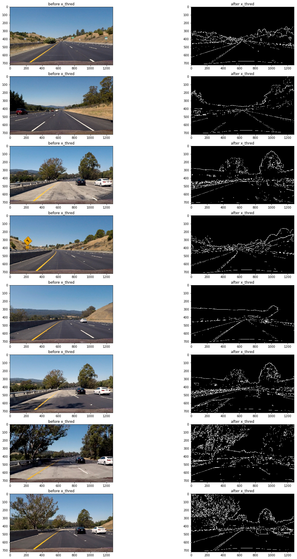
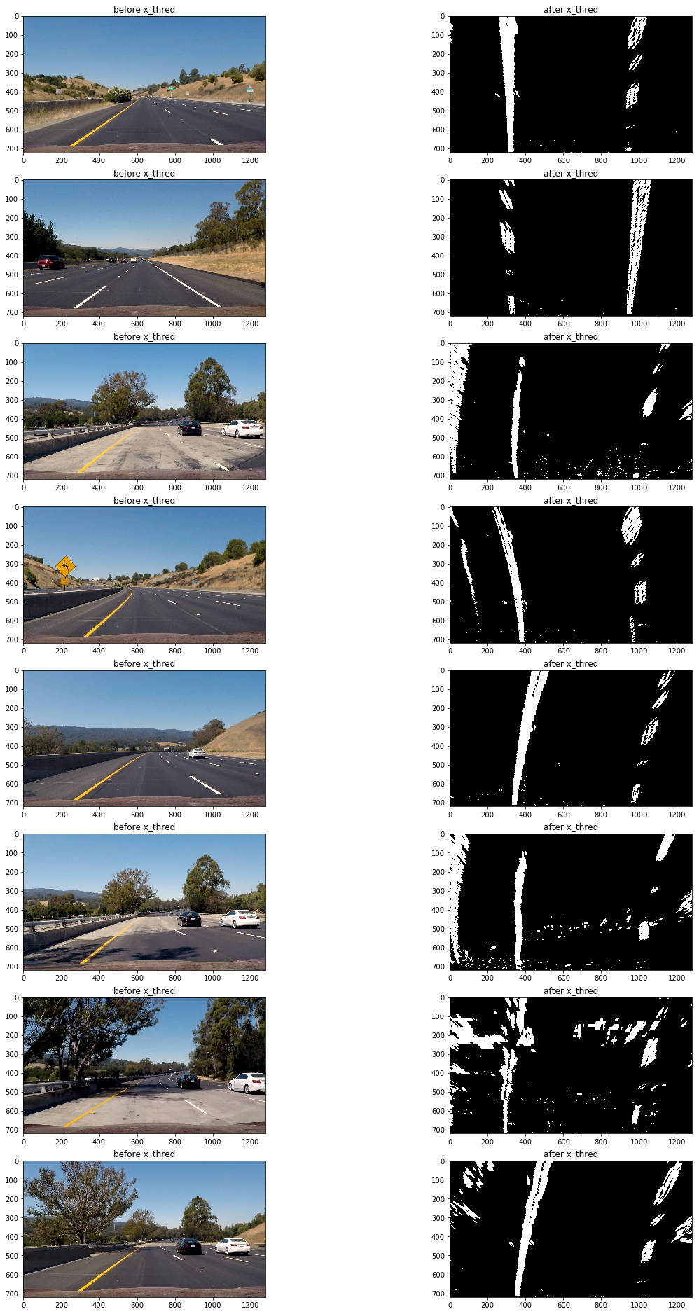
通过测试发现使用x轴方向阈值在35到100区间过滤得出的二进制图可以捕捉较为清晰的车道线:
abs_sobel_thresh(imge,absm,'x',55,200);//sobel边缘识别
以下为使用上面方法应用测试图片的过滤前后对比图:

可以看到该方法的缺陷是在路面颜色相对较浅且车道线颜色为黄色时,无法捕捉到车道线(第三,第六,第七张图),但在其他情况车道线捕捉效果还是不错的。
接下来测试一下使用全局的颜色变化梯度来进行阈值过滤:
void mag_thresh(const cv::Mat& src,cv::Mat& dst,const int& sobel_kernel=3,const int& thresh_min=0,const int& thresh_max=255){
    cv::Mat src_gray,gray_x,gray_y,grad;
    cv::Mat abs_gray_x,abs_gray_y;
    //转换成为灰度图片
    cv::cvtColor(src,src_gray,cv::COLOR_RGB2GRAY);
    //使用cv::Sobel()计算x方向或y方向的导
    cv::Sobel(src_gray,gray_x,CV_64F,1,0,sobel_kernel);
    cv::Sobel(src_gray,gray_y,CV_64F,0,1,sobel_kernel);
    //转换成CV_8U
    cv::convertScaleAbs(gray_x,abs_gray_x);
    cv::convertScaleAbs(gray_y,abs_gray_y);
    //合并x和y方向的梯度
    cv::addWeighted(abs_gray_x,0.5,abs_gray_y,0.5,0,grad);
    //二值化
    cv::inRange(grad,thresh_min,thresh_max,dst);
    // cv::threshold(grad,dst,thresh_min,thresh_max,cv::THRESH_BINARY|cv::THRESH_OTSU);

}
mag_thresh(imge,mag,3,45,150);
结果仍然不理想(观察第三,第六,第七张图片),原因是当路面颜色相对较浅且车道线颜色为黄色时,颜色变化梯度较小,想要把捕捉车道线需要把阈值下限调低,然而这样做同时还会捕获大量的噪音像素,效果会更差。
那么使用颜色阈值过滤呢? 下面为使用hls颜色空间的s通道进行阈值过滤:
void hls_select(const cv::Mat& src,cv::Mat& dst,const char& channel='s',const int& thresh_min=0,const int& thresh_max=255){
    cv::Mat hls,grad;
    vector<cv::Mat> channels;
    cv::cvtColor(src,hls,cv::COLOR_RGB2HLS);
    //分离通道
    cv::split(hls,channels);
    //选择通道
    switch (channel)
    {
        case 'h':
            grad=channels.at(0);
            break;
        case 'l':
            grad=channels.at(1);
            break;
        case 's':
            grad=channels.at(2);
            break;
        default:
            break;
    }
    //二值化
    cv::inRange(grad,thresh_min,thresh_max,dst);
    // cv::threshold(grad,dst,thresh_min,thresh_max,cv::THRESH_BINARY);
}
mag_thresh(imge,mag,3,45,150);
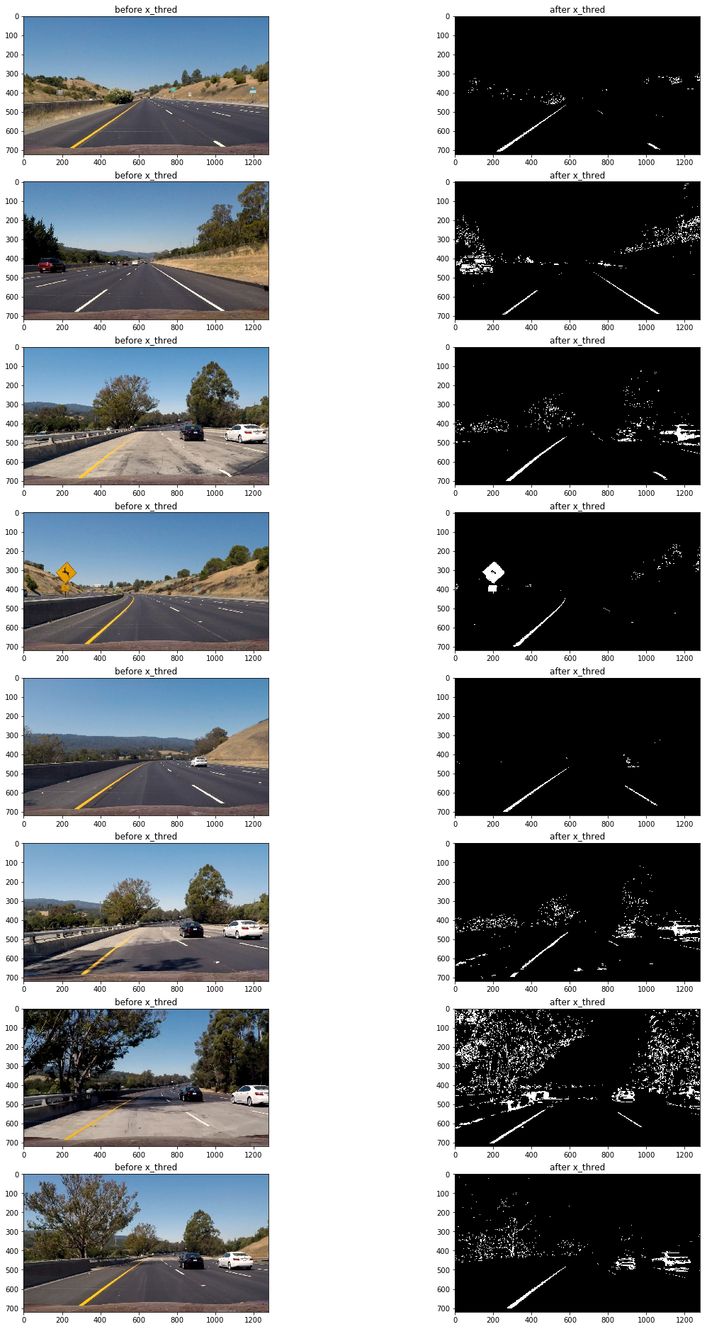
可以看到在路面颜色相对较浅且车道线颜色为黄色的区域,车道线仍然被清晰的捕捉到了,然而在其他地方表现却不太理想(第四,第八张图片)
因此为了应对多变的路面情况,需要结合多种阈值过滤方法。
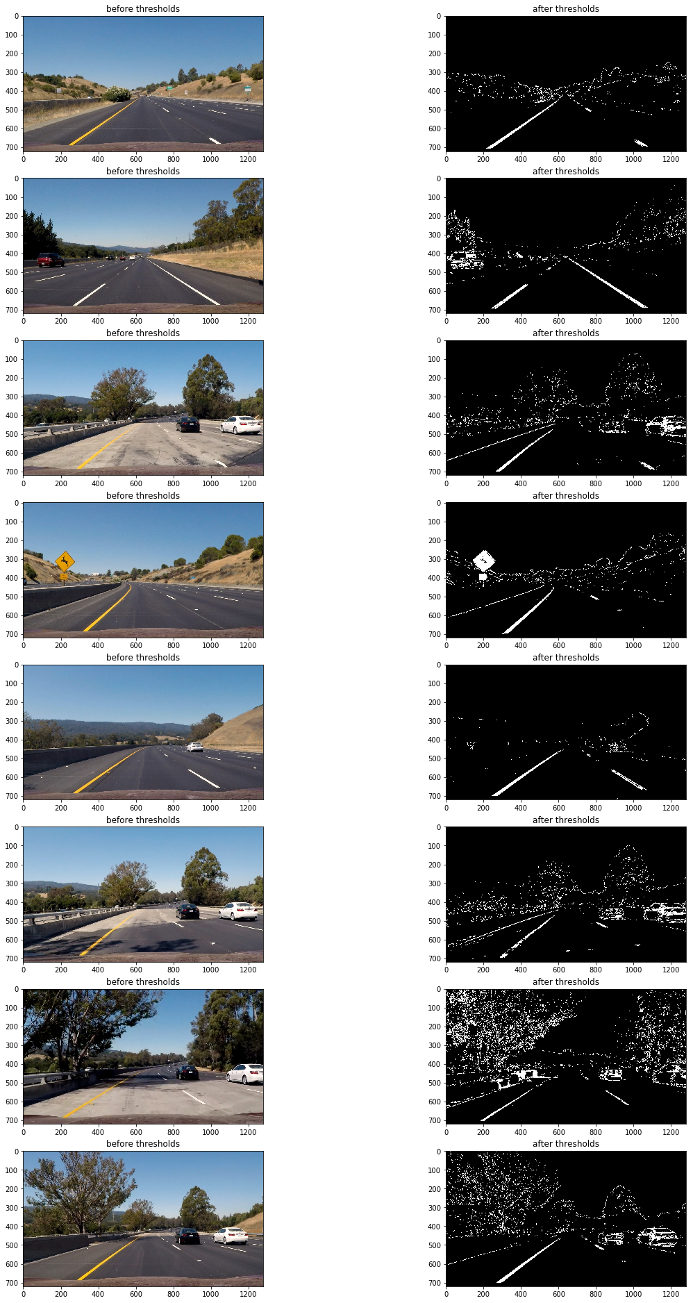
以下为最终的阈值过滤组合:
abs_sobel_thresh(imge,absm,'x',55,200);//sobel边缘识别
mag_thresh(imge,mag,3,45,150);
hls_select(imge,hls,'s',160,255);
dir_threshold(imge,dir,3,0.7,1.3);
luv_select(imge,luv,'l',180,255);
// lab_select(imge,lab,'b',126,127);

imgout=(absm&mag&luv)|(hls&luv);
透视变换(perspective transform)
这里使用”cv::getPerspectiveTransform()“来获取变形矩阵(tranform matrix),把阈值过滤后的二进制图片变形为鸟撒视角。
以下为定义的源点(source points)和目标点(destination points)
| Source | Destination | |:————-:|:————-:| | 585, 460 | 320, 0 | | 203, 720 | 320, 720 | | 1127, 720 | 960, 720 | | 695, 460 | 960, 0 |
定义方法获取变形矩阵和逆变形矩阵:
void get_M_Minv(const vector<cv::Point2f>& src,const vector<cv::Point2f>& dst,cv::Mat& M,cv::Mat& Minv){
    M=cv::getPerspectiveTransform(src,dst);
    Minv=cv::getPerspectiveTransform(dst,src);
}
然后使用”cv::warpPerspective()“传入相关值获得变形图片(wrapped image)
cv::warpPerspective(cimg,imge,M,img.size(),cv::INTER_LINEAR);
以下为原图及变形后的效果:
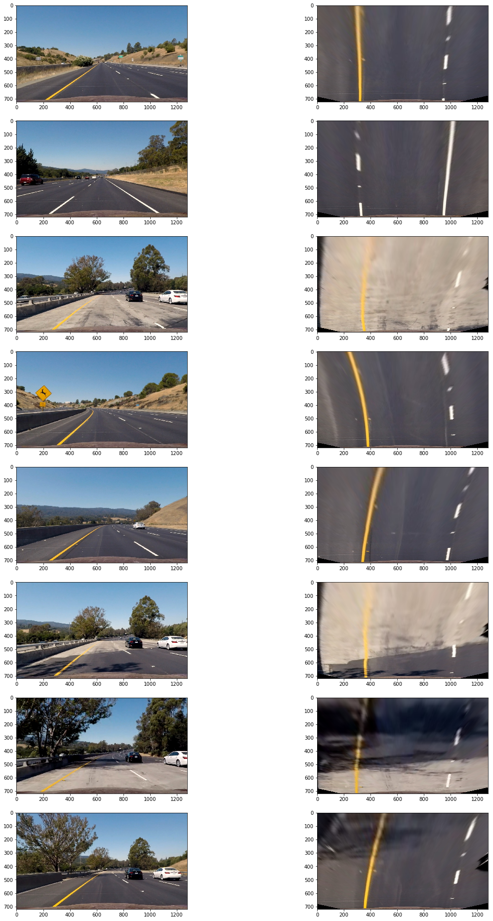
以下为阈值过滤后二进制图变形后效果:
检测车道边界
上面的二进制图还存在一定的噪音像素,为了准确检测车道边界,首先要确定哪些像素是属于车道线的。
首先要定位车道线的基点(图片最下方车道出现的x轴坐标),由于车道线在的像素都集中在x轴一定范围内,因此把图片一分为二,左右两边的在x轴上的像素分布峰值非常有可能就是车道线基点。
以下为测试片x轴的像素分布图:
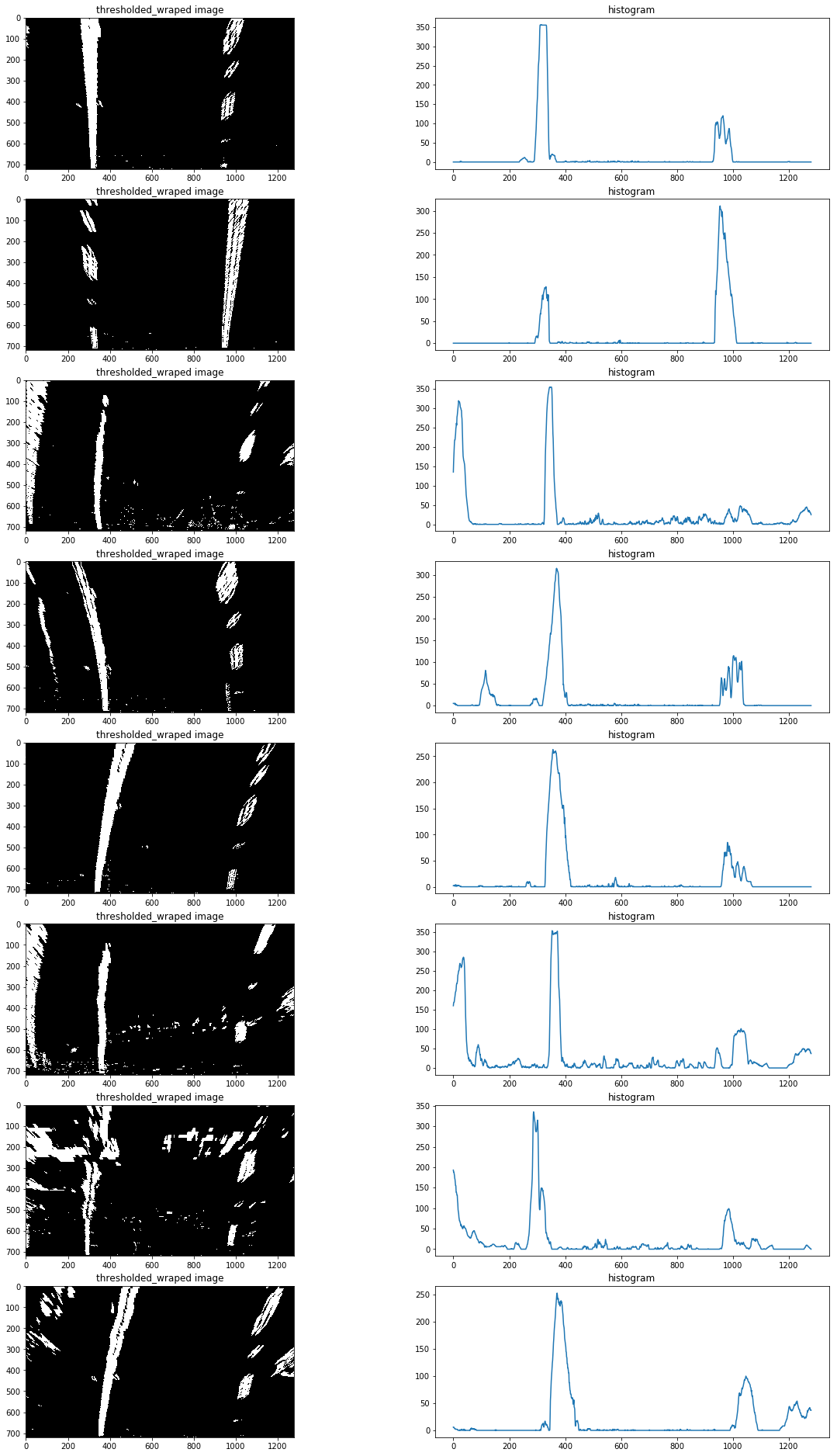
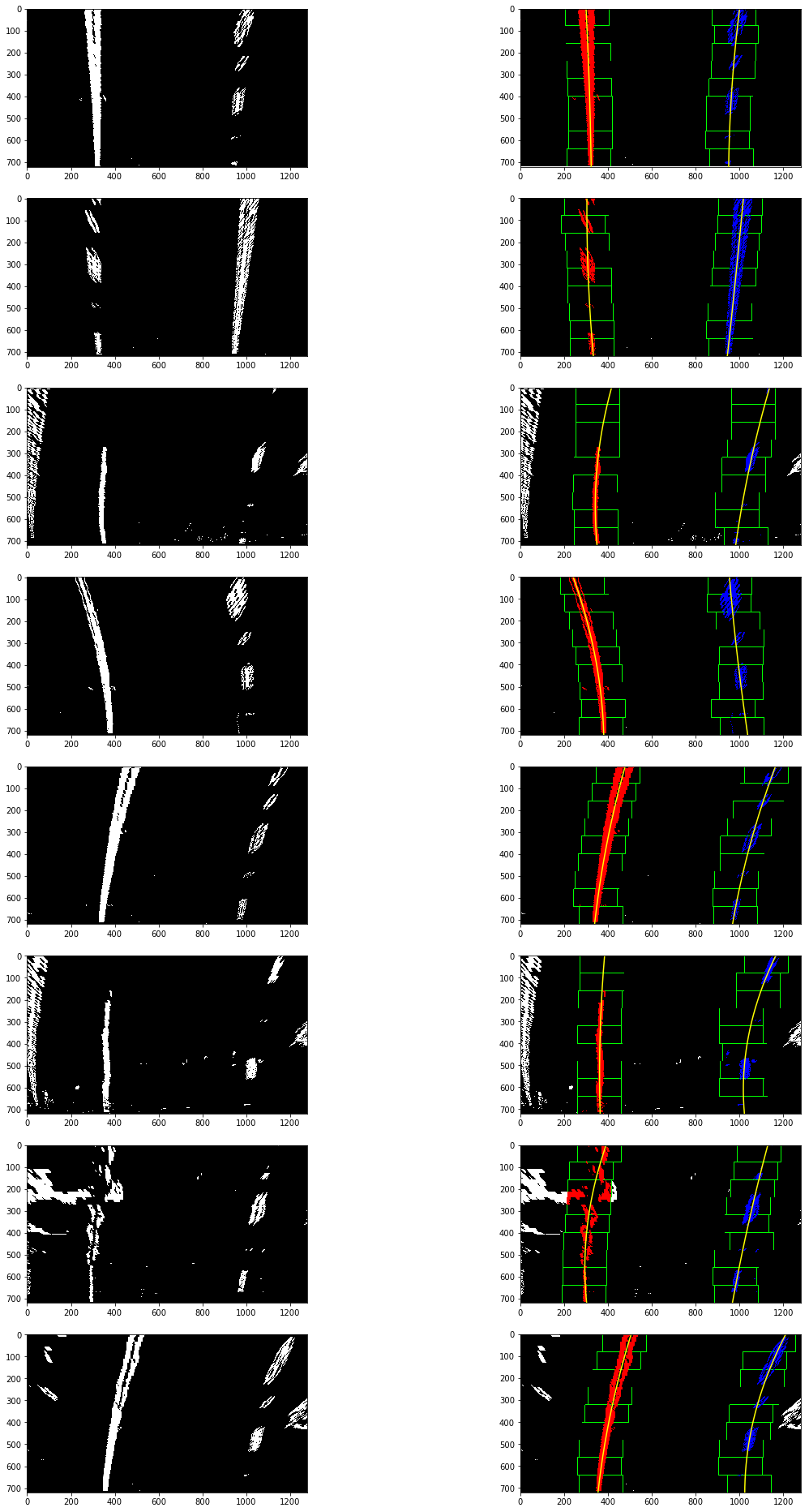
定位基点后,再使用使用滑动窗多项式拟合(sliding window polynomial fitting)来获取车道边界。这里使用9个200px宽的滑动窗来定位一条车道线像素:
void find_line(const cv::Mat& src,vector<cv::Point>& lp,vector<cv::Point>& rp,int& rightx_current,int& leftx_current,double& distance_from_center){
    cv::Mat hist,nonzero,l,r;
    vector<cv::Point> nonzerol,nonzeror,lpoint,rpoint;
    int midpoint;
    cv::Point leftx_base,rightx_base;
    //选择滑窗个数
    int nwindows = 9;
    //设置窗口高度
    int window_height = int(src.rows/nwindows);
    //设置窗口宽度
    int margin=50;
    //设置非零像素坐标最少个数
    int minpix=50;
    //TODO 加入if设置图像连续性,如果leftx_current和rightx_current为零,则认为第一次执行,需要计算该两点,如果已经计算了,则不许再次计算。
    //rowrange图像区域分割
    //将图像处理为一行,以行相加为方法
    cv::reduce(src.rowRange(src.rows/2,src.rows),hist,0,cv::REDUCE_SUM,CV_32S);
    midpoint=int(hist.cols/2);
    //将hist分为左右分别储存,并找出最大值
    //minMaxIdx针对多通道,minMaxLoc针对单通道
    cv::minMaxLoc(hist.colRange(0,midpoint),NULL,NULL,NULL,&leftx_base);
    cv::minMaxLoc(hist.colRange(midpoint,hist.cols),NULL,NULL,NULL,&rightx_base);
    //左右车道线基础点
    leftx_current=leftx_base.x;
    rightx_current=rightx_base.x+midpoint;
    // 提前存入该基础点坐标
    lpoint.push_back(cv::Point(leftx_current,src.rows));
    rpoint.push_back(cv::Point(rightx_current,src.rows));
    for(int i=0;i<nwindows;i++){
        int win_y_low=src.rows-(i+1)*window_height;
        //计算选框x坐标点,并将计算结果限制在图像坐标内
        int win_xleft_low = leftx_current - margin;
        win_xleft_low=win_xleft_low>0?win_xleft_low:0;
        win_xleft_low=win_xleft_low<src.rows?win_xleft_low:src.rows;
        //int win_xleft_high = leftx_current + margin;
        int win_xright_low = rightx_current - margin;
        win_xright_low=win_xright_low>0?win_xright_low:0;
        win_xright_low=win_xright_low<src.rows?win_xright_low:src.rows;
        //int win_xright_high = rightx_current + margin;
        //NOTE要确保参数都大于0,且在src图像范围内,不然会报错
        //NOTE 设置为ROI矩形区域选择
        l=src(cv::Rect(win_xleft_low,win_y_low,2*margin,window_height));
        r=src(cv::Rect(win_xright_low,win_y_low,2*margin,window_height));
        //NOTE 把像素值不为零的像素坐标存入矩阵
        cv::findNonZero(l,nonzerol);
        cv::findNonZero(r,nonzeror);
        //计算每个选框的leftx_current和rightx_current中心点
        if(nonzerol.size()>minpix){
            int leftx=0;
            for(auto& n:nonzerol){
                leftx+=n.x;
            }
            leftx_current=win_xleft_low+leftx/nonzerol.size();
        }
        if(nonzeror.size()>minpix){
            int rightx=0;
            for(auto& n:nonzeror){
                rightx+=n.x;
            }
            rightx_current=win_xright_low+rightx/nonzeror.size();
        }
        //将中心点坐标存入容器
        lpoint.push_back(cv::Point(leftx_current,win_y_low));
        rpoint.push_back(cv::Point(rightx_current,win_y_low));
    }
    //拟合左右车道线坐标
    cv::Mat leftx = polyfit(lpoint,2);
    cv::Mat rightx = polyfit(rpoint,2);
    //计算拟合曲线坐标
    lp=polyval(leftx,lpoint,2);
    rp=polyval(rightx,rpoint,2);
    //计算车道偏离距离
    int lane_width=abs(rpoint.front().x-lpoint.front().x);
    double lane_xm_per_pix=3.7/lane_width;
    double veh_pos=(((rpoint.front().x+lpoint.front().x)*lane_xm_per_pix)/2);
    double cen_pos=((src.cols*lane_xm_per_pix)/2);
    distance_from_center=veh_pos-cen_pos;
    // cout<<"dis"<<distance_from_center<<endl;
    // cout<<lp<<endl;
}
以下为滑动窗多项式拟合(sliding window polynomial fitting)得到的结果:
计算车道曲率及车辆相对车道中心位置
利用检测车道得到的拟合值(find_line 返回的left_fit, right_fit)计算车道曲率,及车辆相对车道中心位置,代码在find_line中:
    int lane_width=abs(rpoint.front().x-lpoint.front().x);
    double lane_xm_per_pix=3.7/lane_width;
    double veh_pos=(((rpoint.front().x+lpoint.front().x)*lane_xm_per_pix)/2);
    double cen_pos=((src.cols*lane_xm_per_pix)/2);
    distance_from_center=veh_pos-cen_pos;
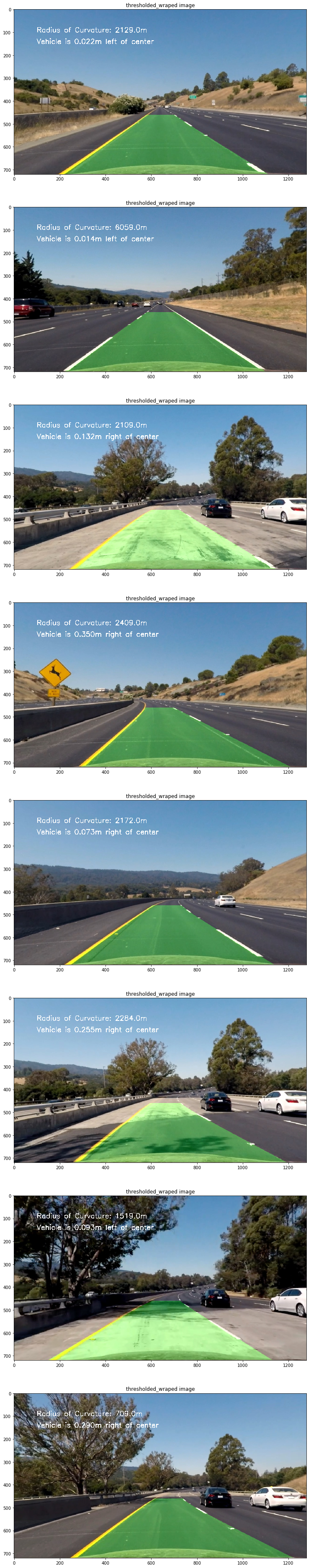
处理原图,展示信息
使用逆变形矩阵把鸟瞰二进制图检测的车道镶嵌回原图,并高亮车道区域,使用”cv::putText()“方法处理原图展示车道曲率及车辆相对车道中心位置信息:
void draw_area(const cv::Mat& src,vector<cv::Point>& lp,vector<cv::Point>& rp,const cv::Mat& Minv,double& distance_from_center){
    vector<cv::Point> rflip,ptr;
    cv::Mat colormask=cv::Mat::zeros(src.rows,src.cols,CV_8UC3);
    cv::Mat dst,midst;
    //绘制车道线
    cv::polylines(colormask,lp,false,cv::Scalar(0,255,0),5);
    cv::polylines(colormask,rp,false,cv::Scalar(0,0,255),5);
    //反转坐标,以便绘制填充区域
    cv::flip(rp,rflip,1);
    //拼接坐标
    cv::hconcat(lp,rflip,ptr);
    //绘制填充区域
    const cv::Point* em[1]={&ptr[0]};
    int nop=(int)ptr.size();
    cv::fillPoly(colormask,em,&nop,1,cv::Scalar(200,200,0));
    //反变形
    cv::warpPerspective(colormask,midst,Minv,src.size(),cv::INTER_LINEAR);
    //将车道线图片和原始图片叠加
    cv::addWeighted(src,1,midst,0.3,0,dst);
    //绘制文字
    cv::putText(dst,"distance bias:"+to_string(distance_from_center)+"m",cv::Point(50,50),cv::FONT_HERSHEY_SIMPLEX,1,cv::Scalar(255,255,255),2);
    cv::imshow("video",dst);
    // cv::waitKey(10000);
}
以下为测试图片处理后结果:
以下为处理后测试视频链接: